Many thanks to Murray ZL1BPU for the excellent revision of the following text
Self made Front Panel
The electronics industry uses several methods for labelling front panels and enclosures, including screen printing, press forming, erosion, lasers etc.. The common factor of these techniques is that they are generally beyond the home constructor. Having these parts specially made commercially can be very expensive, and the only alternative is standardized scales and fonts.
For this reason, the design of an attractive front panel generally neglected, and once a design is built and operating as expected, very often the circuit is placed in an existing used housing that soon looks like a Swiss cheese, and more often than not is labelled using a felt-tip pen or stick-on labels This article describes how you can improve this situation - with detailed instructions for building front panels with a semi-professional look.
The front panel should consist of three stages:
| Stage (Ebene) A: | Mounting of electrical/mechanical components (potentiometers, switches, plugs and sockets, displays etc.) required for information input and output. |
| Stage (Ebene) B: | Covering the mounting devices (screws, nuts, rivets, unwanted holes etc.) |
| Stage (Ebene) C: | Labelling, including text, scales, symbols, lines etc. |
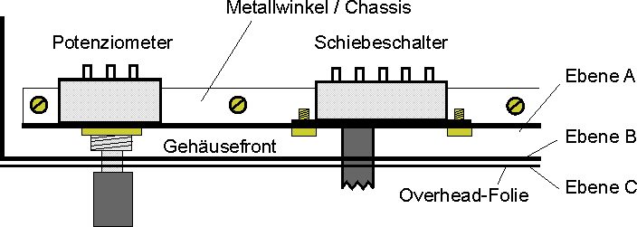
Fig. 1: Order and function of the three stages
(from diagram: potentiometer, mounting plate / chassis, cabinet front, slide switch, stage A/B/C, overhead transparency)
With many home brew projects stage A is a simple, where an additional metal plate within the housing supports the components, and stage B is housing front itself. For a perfect look, only stage C is missing.
An alternative order of construction is also common. A cover plate (stage B) as part of the housing is mounted in front of a chassis (level A), and stage C is omitted.
The first step in creating stage C is that a digital drawing must be made for stage B ( and/or A). The graphics program Corel Draw is useful for developing technical drawings and can reverse text (essential feature for this project). The process will be described on the example of a radio front panel.
Fig. 2: Drawing of stage B (left hand section)
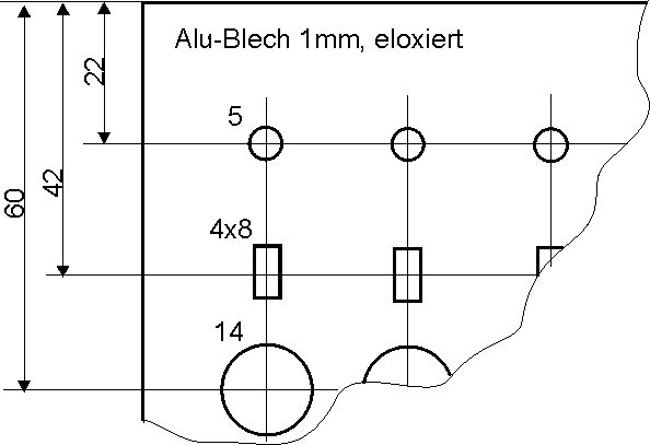
(from diagram: 1mm Al sheet, anodized)
First save a file copy of the drawing that shows stage B(A). Then add the labelling (text, scales, symbols, lines etc) to the drawing. Limits are only set by the graphic program performance and your own imagination. Do not forget to place four crosses that indicate the outer front panel size. Next delete all graphic elements that are no longer needed. These are the holes, drill markings etc. as well as dimensions, arrows, material data and handling hints. The level C file should then contain only the labelling and four crosses. At the end of the PC work select all the objects, group them, flip them horizontally and store the drawing as the stage C file. Read the below remark before printing the level C drawing on a laser-printer overhead transparency at 1:1 scale.
Remark: Ensure that the laser printer is capable of printing on transparencies. If not, do not attempt it. The transparency may melt on the printer drum (the most expensive part). Of course the transparency is must also be suitable for laser printer use. I was successful with the Minolta-QMS PagePro 1200W printer HP Color LaserJet (5/5M, 4500, 8500) transparencies.
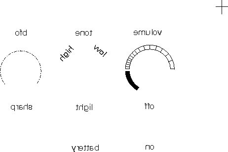
Fig. 3: Mirrored level C (left hand section)
Cut the transparency to the outer front panel dimension, but do not cut anything else yet. Work from the side of the print without toner in order to avoid scratches. Use a steel ruler and a scalpel for cutting the transparency to size. The crosses are helpful for orientation when cutting. The ruler should be moved to the crosses from outside the panel area. The transparency is mirrored for printing so that the easily damaged labelling will be behind the transparent layer and protected from damage.
An anodized aluminium sheet is recommended as front panel. This needs to be machined and finished as in the stage A drawing, with all final holes etc. Now glue the transparent layer to the front panel. Use a transparent latex type glue and cover the whole front panel. You may need to experiment to find a suitable transparency- friendly glue which does not dissolve the toner. UHU All-purpose Transparent is suitable.
Flip the resized transparency horizontally, and carefully press it onto the cover or front panel from left to right. Squeeze and remaining bubbles out carefully to the edge or the nearest panel hole using a wooden spatula. Wipe off any surplus adhesive. The process must be repeated several times as the adhesive dries. This takes longer than is usual, as the adhesive solvent cannot be absorbed into the metal or transparency. A small press (book press or flower press) is useful for encouraging a smooth surface. Place another transparency on top, then a smooth sheet of some hard material between the panel and the press. Remaining adhesive can be removed with alcohol or white spirits. Finally, carefully remove the transparency above the panel holes using the scalpel. Remove the transparency in tiny pieces in order to avoid lifting the transparency from the substrate. To get clean edges to the larger holes, use a narrow blade, and operate the scalpel blade against the edge of the hole in the metal substrate at just the right angle. If everything goes as planned, the result should look similar to this...
Fig. 4: Cover with transparency glued on
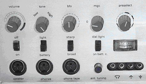
Remark: Tests with spray-on adhesive and a colour laser printer are in preparation. </