I would be grateful for a professional translation or correction of the following text. Please E-Mail to Delta Lima 2 Yankie Echo Oscar @ Queen Romeo Papa 4 Uniform .Delta Echo
40 m Band Receiver without ICs
Today it is very difficult or quite impossible to purchse components that are best suited for QRP circuits. Mixer ICs like the NE602/612, ceramic filters SFE7.02, RF power transistors up to 5W belong to this group. In order to avoid this problems, I have used for the following circuit discretes components which are offered by several dealers or distributors. The only exception is a variable capacitor, which can be substituted easily by a varactor diode. The following circuit consists out of five sub-modules.
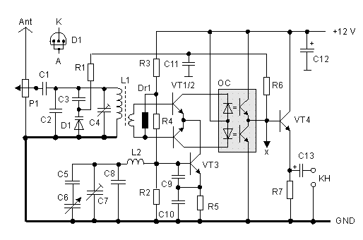
The original circuit without a varactor diode has shown an unlikely effect. Depending upon the VFO tuning frequency the DC voltage at test point x changes between +Ub (12 V) and GND (0 V). It amounts to Ub/2 if the VFO frequency corresponds to the resonant frequency of the pre-selector. In this case the audio signal is loudest. Close to +Ub and GND the audio signal is short circuit by one of the photo transistors. The described effect is based on the fact that basically always something RF of the VFO enters via the VT1/2 transistors into the pre-selector L1/C4. When mixing two signals with the same frequency also a DC voltage appears that is proportional to the phase difference. This DC voltage causes the above described effect.
Fig. 1: Receiver with only discrete components

With the increased quality Q of the pre-selector also the gain and selectivity (audion principle) increases, which is absolutely positive. A shortcoming is that the DC voltage triggers the photo transistors when tuning. The later can be compensated by tracking the pre-selectors resonance frequency with the aid of the DC voltage. The tuning range increases then from before 10 kHz to more than 100 kHz and the voltage at the test terminal x stays within the limits of +2 to +10 V.
Alignment of this circuit is not quite simple. One has to perform six steps in the below mentioned sequence:
If not stable operating point is reachable by setting C4, the reasons could
be the following.
| a.) | With capacity variation of D1 the resonance frequency does not move into the direction of the VFO frequency; it moves into the opposite direction instead. Exchanging the primary leads of L1 causes relief. |
| b.) | A second source of error could be, that one cannot find the resonance point of the pre-selector. If so, then exchange C2 against a capacitor with a higher or lower value (calculate or try). |
| c.) | Insufficiant feedback can result in a low DC level ( Ux < + 6V ) at terminal x. To enter a bit more RF energy into the pre-selector, connect one end of a short insulated wire to the basis of VT3 and put the other end through the L1 toroid. Too close coupling results in self-oscillation of the circuit. |
VT4 operates as an impedance converter and allows connecting low impedance headphones. For preferred reception of CW and SSB it is recommended to insert a suitable audio filter into the signal path. The current consumption is about 10 to 20 mA depending on the collector current of the photo transistors. With feeding the receiver from a none-stabilized power supply of +9 V to +15 V the VFO frequency changes only slightly.
| Parts | Value |
|---|---|
| R1,6 | 100 kOhm |
| R2,3 | 1 kOhm |
| R4,5,7 | 560 Ohm |
| P1 | 220 Ohm, linear |
| C1 | 10 pF |
| C2 | 220 pF |
| C3 | 470 pF |
| C4,7 | 5 ... 80 pF, trim capacitor |
| C5 | 18 pF |
| C6 | 5 ... 50 pF, variable capacitor |
| C8 | 100 pF |
| C9 | 680 pF |
| C10 | 1 nF |
| C11 | 1 uF |
| C12 | 100 nF |
| C13 | 10 uF |
| Dr1 | 100 uH |
| L1 | T44-2 17 Wdg. prim. and 3 turns sec. |
| L2 | T50-2, 27 turns |
| D1 | BB204 varactor diode e.g. |
| VT1/2 | 2N3904, identical current gain |
| VT2,4 | 2N3904 |
| OC | IRD74, CNY74 .... dual opto coupler |
| KH | Headphones Ri > 64 Ohm (2 x 32 Ohm) |
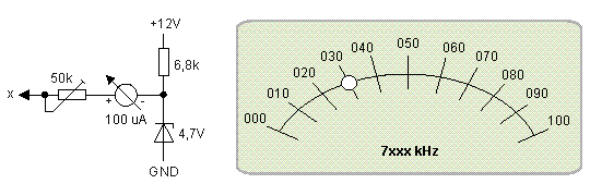
Because the tuning voltage at the test terminal x changes quite linear with the VFO frequency, it can be used for driving a frequency display. Adjust with C4 the zero point of the uA meter at 7000 kHz. It should amount to 4,7 V measured at x. The 50 kOhm trim potentiometer is used for setting the 100% position at 7100 kHz. The use of a 4,7 V the Zener diode in the lower section of the bridge arrangement makes the reading insensible against supply voltage changes. Between Ub=+9 .... +15 V the indicator remains on the desired frequency mark.
Fig. 2: Frequency Indicator

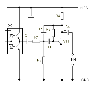
Who will only listen to CW should try the below discribed audio filter. The filter is reasonably narrow and provides additional 32 dB gain at 750 Hz. This 32 dB together with 10 dB from the mixer and 40 dB from the opto coupler signal pick up make a total amount of 82 dB. By reason of the VT1 high output impedance headphones with Ri > 4 kOhms should be connected.
Fig. 3: Simple CW Filter

| Parts | Value |
|---|---|
| R1,4 | 4,7 kOhm |
| R2 | 1,5 kOhm |
| R3 | 680 kOhm |
| C1 | 1 uF |
| C2,3 | 10 nF |
| C4 |