I would be grateful for a professional translation or correction of the following text. Please E-Mail to Delta Lima 2 Yankie Echo Oscar @ Queen Romeo Papa 4 Uniform .Delta Echo
AGC and S-Meter
You can build an automatic gain control AGC for the superhet receiver with
only a few additional components. The first AGC circuit is more universal. It
is suitable for audio amplifiers with dual op amps like TL072, TL082, NE5532
and the broadband amp NE592 too.
The second circuit is only suitable for AF amplifiers with dual op amps because
it requires equal DC voltage levels at inputs and outputs as well as
insensitivity of them against supply voltage changes. This two conditions
aren't available for an audio amplifier based on the NE592.
Both AGC circuits have a response time of about 10 ms and a hold-on time of 2
s. I didn't show the op amp circuitry in favour of a simple presentation of the
AGC schematic
Variant 1:
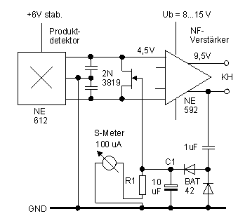
The AGC is capable in reducing the AF stage output signal down to 3 Vss in case of strong receive signals. Week receive signals lead in a low DC voltage at C1 due to the low AF signal level. FET's, such as the 2N3819, are fully turned off at - 4,8 V gate voltage. Strong receive signals produce a control voltage of 3 ... 4 V maximum. The gate voltage drops against zero, causing the FET to conduct. The latter results in a partial short-circuit of the AF amplifier input signal and hence in a reduced audio volume.
Fig. 1: Universal AGC circuit

Whoever likes, can set a sensitive 50 ... 100 uA meter in series with the discharging resistor R1 for indicating the relative signal strength "S-meter". R1 should be reduced from originally 220 kohms down to around 100 kOhm, whereby the hold-on time gets a little bit shorter then.
Variant 2:
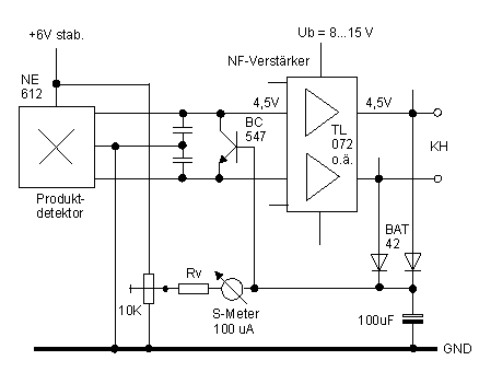
The second AGC circuit can eliminate volume changes much better compared to the first circuit. The reason of this is the higher controller gain (bipolar transistor instead of a FET). Even in case of very strong receive signal, the measured AF stage output voltage against ground, is only 2 Vss at its maximum. No coupling capacitor is needed because all DC levels at the dual op amp inputs and outputs have the same rate.
Fig. 2: AGC circuit only for TL 072 etc.

With a positive AF signal swing of >1 Vs the 100 uF capacitor will get
charged up to 5.2 V. The transistor conducts by means of the now flowing base
current. This causes here also a volume reduction at strong receive signals.
Calibrating the S meter isn't so easy like the first circuit. There is less
voltage change available at the capacitor. Zero point adjustment with the 10
kohm trim potentiometer must be done first. Rv is responsible for the pointer
swing. The Rv resistance has to be defined by something trying, it is about 4,7
kohm.