I would be grateful for a professional translation or correction of the following text. Please E-Mail to Delta Lima 2 Yankie Echo Oscar @ Queen Romeo Papa 4 Uniform .Delta Echo
Analogue Frequency Display
Especial QRP receiver with a VXO /VFO have a potentiometer or variable
capacitor reading that isn't linear referring to the frequency. Depending on
the tuning element one can get an linearity improvement by adding resistors,
diodes or capacitors. Quite impossible is a linearisation for a VXO with its
variable capacitor and inductance in series.
A further problem is, that there are a number of knob turns between Cmin and
Cmax when using a multi-turn potentiometer for getting the varicap diode
control voltage. The later is very good for fine tuning but not so good for
preparing a none-linear spiral shaped scale round the tuning knob. The same
problem exists for a twin gang variable capacitor.
For nearly accurate reproduction of the desired RX/TX frequency, one can draw a none-linear scale, can use a calibration chart with degree to frequency values, can spend time and brain for linearising the tuning components or can measure the oscillator frequency directly with more or less high expenditure of additional components. Using a digital frequency counter module is the classic method, but in my opinion this is over-designed for QRP devices. Counter modules might have the same number of components as some simple QRP transceiver. Depending on the module type they are current hungry and can possibly disturb the reception when insufficiently shielded.
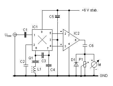
The following circuit is a compromise between scaling of the potentiometer or variable capacitor and the installation of a digital frequency counter with LCD or LED display. The analogue frequency display has an acceptable linearity and accuracy, consists only out of 12 components and needs minor supply current.
Fig.1: Schematic of the analogue frequency display

Function
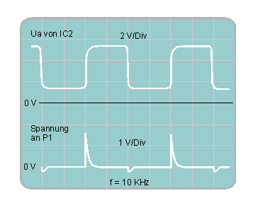
A voltage Vosc = 50 ... 200 mVpp is taken from the VFO/VXO and applied via C1 onto the mixer input. IC1 mixes this signal with the signal from its internal crystal oscillator Q1. The quartz crystal frequency must correspond to the VFO/VXO frequency at the low band edge. The low frequent sinusodial differential signal of about some hundred mVpp is now converted into a rectangular signal by maximum gain of the OP amp IC2. After differentiation by P1/C6, suppression of the negative pulse by D1 and integration by the instrument M you'll get a pointer reading proportional to the differential frequency.
The circuit was designed for a VFO/VXO initial frequency of 14294 kHz and 20 ... 50 kHz tuning range. For a different initial frequency the crystal and C3/C4 have to be changed. A smaller or larger tuning range requires a different capacitor C6.
Fig. 2: Signal at the OP amp output and differentiator

Due to the rectangular signal and needle pulses a noise spectrum is generated also by this circuit. But it isn't so strong compared to the one of a digital counter operating with very fast rising and falling signals. The installation in a small metal case is recommended anyway, especially for receivers that were built for the lower short wave bands.
Power supply
The analogue frequency display needs a stabilised voltage of typically +6 V ( 5 .... 7 V). Such a voltage is of sure still existing in QRP devices for the VFO, VXO or mixer supply. The measured circuit current consumption was 3,7 mA at +6 V.
Parts list
| Parts | Value |
|---|---|
| P1 | 2,5 KOhm, 10 turn trim pot |
| C1 | 50 pF |
| C2 | 0,1 uF |
| C3, C4 | 100 pF |
| C5 | 47 uF, 10 V |
| C6 | 4,7 nF |
| L1 | Cylindrical body, 4 mm diameter, 12 mm hight= ,
approx. 2 x 16 turns, ferrite core |
| D1 | BAT42 |
| IC1 | NE612 |
| IC2 | TL071 |
| Q1 | 14318 kHz |
| M | Moving coil instrument ,100 uA |
Alignment
At the low frequent band edge (f_osz = f_min )
the mixer output signal should be near to 0 Hz. If the crystal doesn't fit, you
have had tough luck and must investigate some money in a special produced
crystal. Suppose the crystal frequency is only a few kHz far from a standard
frequency, you can pull it by a variable capacitor or inductance to the desired
value.
At the high frequend band edge (f_osz = f_max) the instrument M has
to be aligned to full scale (100 uA = 100 %) with the trim pot P1.
The C6 / P1 combination allows 20 ... 50 kHz tuning range. A 2,2 nF capacitor
is necessary for 100 kHz tuning range.
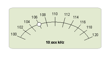
Who doesn't mind a GM47 transceiver instrument scale with reverse calibration ( low frequent band edge is right hand ) needs only a 14318 standard crystal. L1 is necessary for a usual scale with rising frequency values from left to right (see fig. 3). The shown values from (10)100 to (10)120 kHz are caused by the 4194 kHz intermediate frequency.
Fig. 3: Calibration example of the 30 m transceiver GM47 scale
