I would be grateful for a professional translation or correction of the following text. Please E-Mail to Delta Lima 2 Yankie Echo Oscar @ Queen Romeo Papa 4 Uniform .Delta Echo
Power Supply for small Tube Amplifiers
Safety Instructions
Caution mortal danger: The following circuit operates at a mains voltage of 230 Vac. Because of rectification some of the components conduct dc voltage of more than 322 V. Work has to be carried out only if the circuit is disconnected from the mains and de-energized. Note that capacitors located to the primary and secondary side can be charged with high voltage for several seconds even after switching of the mains voltage.
For tube amplifiers, independent if HF or AF, it is more difficult to find
50 Hz transformers with appropriate output voltages for a reasonable price.
Associated high-inductive chokes are also very expensive. 100 Euro for the
components of a conventional power supply aren't unrealistic.
From this misery the following project arises. It is based on a small
electronic transformer for low voltage halogen bulbs and can provide the tube
amplifiers anode voltage and filament voltage. Such transformers are cheaply
available for about 15 Euro in each do-it-your-self store. For lack of space at
the modification one should necessarily purchase a type with a toroidal core.
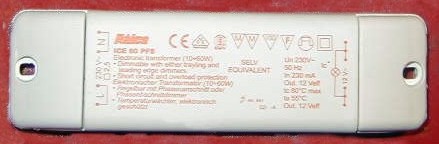
Fig. 1: Electronic transformer (20 ...60W)
Do not mix up an electronic transformer with a switching power supply. Some essential features are missing, but which are not necessarily needed for the before mentioned application . There are no control loops for stabilizing the output voltage in case of load changes and mains voltage drops. Furthermore some types are not short-circuit-proof.
Comparison 50 Hz < > 40 kHz
In contrast to a classical 50 Hz power supply there are a number of advantages not to be sneezed at operation and for experiments with a power supply that is based upon an electronic transformer.
There are as well some disadvantages, which I do not want to conceal.
Circuit Principle
The circuit diagram of an electronic transformer is very clear. After the
current compensated choke a NTC resistor follows for inrush current limitation.
The 230 VAC rectifier provides a 100 Hz pulsating DC voltage (without C1) for
supplying the DC/AC converter. The converter operates in the well known half
bridge configuration. Both bipolar transistors form the left branch of the
bridge and both series arranged 0.1 uF capacitors the right branch. Between the
branches the output transformer is located.
The transistors together with a small auxiliary transformer (toroidal) act as a
freerunning oscillator. Observable for this configuration is that the base
current rises automatically with the output current. Thus the gain loss with
high collector current will be compensated.
The small box marked with "Start-Up" contains a simple start-up
circuit. A small pulse generator consisting of a diac, a capacitor and some
diodes affects the oscillator start after power on.
The drawing below shows the electronic transformer on gray background.
Filtering capacitor C1 (dotted line) and the secondary rectifiers shown on pink
background have been added.
Abb. 2: Electronic transformator with subsequent
secondary rectification
First Measurings
The left hand image was recorded at the unchanged electronic
transformer with a 20 W halogen bulb as load. Light filtering of the rectified
mains voltage with only 2 x 0.1 uF in series causes strong 100 Hz modulation.
The rms value of the modulated 40 KHz alternating voltage corresponds to the 12
V stated on the plastic case.
After inserting the 220 uF / 385 V capacitor C1 the AC voltage looks more
friendly (see right hand image). There was only a small 100 Hz hum of 140 mVss
measurable. With 18 Vss at 8 turns one gets a voltage of 2.25 V per turn. This
value is important for the subsequent calculation of secondary windings for
other voltages.
Abb. 3: Output alternative voltage with and without
charging capacitor C1
Providing the Anode Potential
Under consideration of voltage loss the following number of turns is required for an anode potential of 270 VDC provided by a voltage doubler for example.
N1 = 270 VDC / 2 x 2.25 = 60
4 x 15 turns (quadrofilar) have been wound on the before desoldered output transformer. Start and end of the four partial windings have been determined with an ohmmeter. A series connection then makes 60 turns. The calculation was confirmed by a load check with 60 W. With this load the circuit was able of providing 260 VDC at the output.
The voltage doubler was chosen in order to keep the turns count as low as possible. Despite of removing the original secondary windings (2 x 8 turns, bifilar) the output transformer offers only little space for new coils. A quadrofilar winding facilitates winding the toroidal, because one has to thread the wire bundle only 15 time through the toroidal for 60 turns secondary.
Providing the Filaments Voltage
According to the application one can use a regulated or unregulated DC voltage directly the 40 kHz alternating voltage.
6.3 V direct voltage (unregulated)
With only a few components (see drawing) the well known full-wave center-tap
rectifier circuit was prepared. A choke and a charging capacitor suppress the
40 kHz rectangle completely and reduce the superimposed 100 Hz ripple voltage.
2 x 3...4 turns bifilar are sufficient for providing a 6.3 V filaments voltage.
Other voltages as there are 12,6 V or 40 V etc. are no problem due to the low
turns count. For the carrying out some tests a gray computer flat cable with 2
wires was used.
As the output voltage is DC, wire-wound power resistors for dissipating
superfluous volts are suitable in this case.
6.3 V direct voltage (regulated)
Alternatively one can generate a regulated direct voltage. For this only 2 x 5 turns are required for feeding a subsequent voltage regulator of the type LM317. The regulator input voltage amounts to about 10 V. The output voltage can be adjusted to exactly 6.3 V with the aid of to resistors located close to the LM317.
6,3 V alternating voltage
With just 3.. 4 turns you can provide a 6,3 V / 40 kHz alternating voltage
for AF/RF power tubes. For exact adjustment one has to apply a quarter or half
turn. At 40 kHz alternating voltage please do not use wire-wound power
resistors (inductivity) for dissipating superfluous volts.
Crosstalk effects between filaments an cathode due to parasitic capacity, are
much worse at 40 kHz with 150 mVss ripple voltage as for 50 Hz heating with an
alternating voltage of 6.3 Vrms. The later is, however not so critical for
AF/RF finals and phase inverters due to the low again and operating mode
(push-pull, differential ... ).
Tube for pre-amplifiers should not be supplied with a 40 kHz filaments voltage.
High gain of pre-amplifiers lead to inadmissible high portion of a 100 Hz
modulated 40 kHz alternating voltage at the anode.
Parts List
| Parts No. | Value |
|---|---|
| RC1 | 33 nF + 12 Ohm (1 W) |
| C1 | 220 uF, 385 V |
| C2, 3 | 220 uF, 200 V |
| C4 | 1000 uF, 25 V |
| L1 | 2 x 3 turns, bifilar |
| L2 | 4 x 15 turns, quadrofilar (series connected) |
| Dr1 | 10 uH, ca. 25 turns, 1 mm Cu wire on a ferrite rode D=5 mm, L=30 mm |
| D1 | Schottky dual-diode 30A / 40V stripped from a AT SMPS, e.g. CTB 34, STP 30L 40CW, SI5SC4M |
| D2, 3 | BY289, 400 V |
| F1 | 3,15 AT |
| F2 | 0,5 AT |
Provisional Assembly
There is at the moment only provisional assembly for 6.3 VDC filaments voltage and 260 VDC anode voltage. The simulated load with a 230 V / 60 W bulb and two defective EL 84 tubes, amounts to 10 W for the heating and 70 W for the anode circuit. The increase of temperature of the switching transistors remains in allowed area. It corresponds to the value when operating tree halogen bulb lamps with 20 watts each. All componets at the secondary remain cool too.
Fig. 2: Provisional assembly for secondary rectification