Many thanks to Murray ZL1BPU for the excellent revision of the following text
Simple IF Amplifier
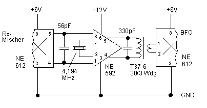
In this circuit, an NE592 acts as an IF amplifier. DC coupling between mixer and amplifier is practical beacuse different + 6 V and + 12 V supply voltages are used. The voltage at the differential input is about 4.5 V. A narrow bandpass filter for the intermediate frequency is achieved using only one crystal as the reactive element. Maximum IF gain is at the crystal series resonance, where the crystal impedance is very low. The capacitor across the amplifier input is intended to suppress mixing products that have a higher frequency than the IF. You cannot do without this cap because parasitic stray capacitance in parallel with the crystal causes unwanted amplification at frequencies higher than the crystal resonance, and thus degrades the IF selectivity. The parallel resonant circuit at the output is tuned to the IF frequency, and serves to attenuate unwanted skirt signals which are due to resonant poles adjacent to the crystal fundamental frequency. A 100 ... 220 Ohm resistor in series with the crystal can be used to improve the filter skirt characteristic.
Fig. 1: 4,194 MHz IF amplifier with a DC coupled mixer IC

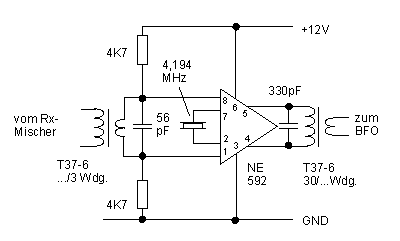
Minor circuit modification is necessary if a ring diode mixer is used to drive the IF amp input. Transformer input is used for impedance matching. The 2 x 4.7 kOhm resistor voltage divider at the transformer secondary provides biasing (Ub/2) for both NE592 inputs. A single 4,7 kOhm resistor connected to a +6 V source would be an alternative arrangement.
Fig.2: IF amplifier with a transformer at its input

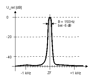
The IF filter has a bandwidth of 150 Hz at -6 dB, provided the amplifier operates in its linear range. When overloaded, the bandwidth becomes much broader, but this does not happen during normal operation. In a typical receiver the amplifier sees only weak input signals, as opposed to the tests carried out with stronger signals.
Fig. 3: IF bandpass filter characteristic at fr=4,194 MHz
